I thought of making a robot that walks on four legs which was a very interesting field to do projects in.
It is interesting and challenging to make this project work properly and gives a satisfaction of achieving such a goal like this.
3D printing
I started by 3d printing some parts, because it is harder to make them by hand. I used PETG on the 3d printer as it is strong and doesn’t warp.
There is four 3d printed parts that are used in the project.
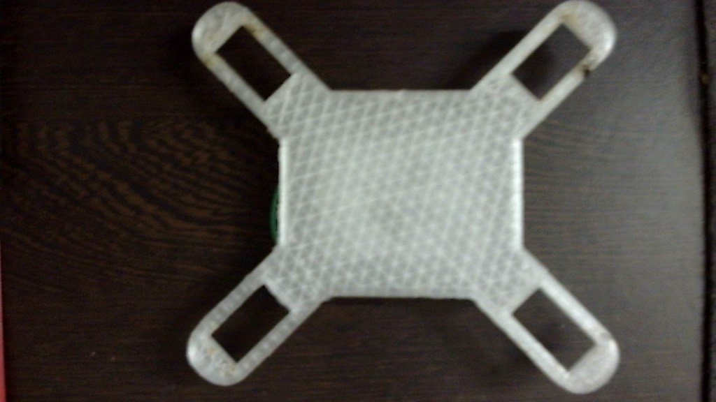
This is the frame.
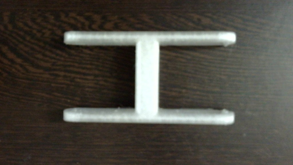
This is the part that connects the frame to the legs its also known as the femur and there are 4 of these.

This is the block that connects the leg to the femur and the claw which is known as the patella and there are 4 of these.
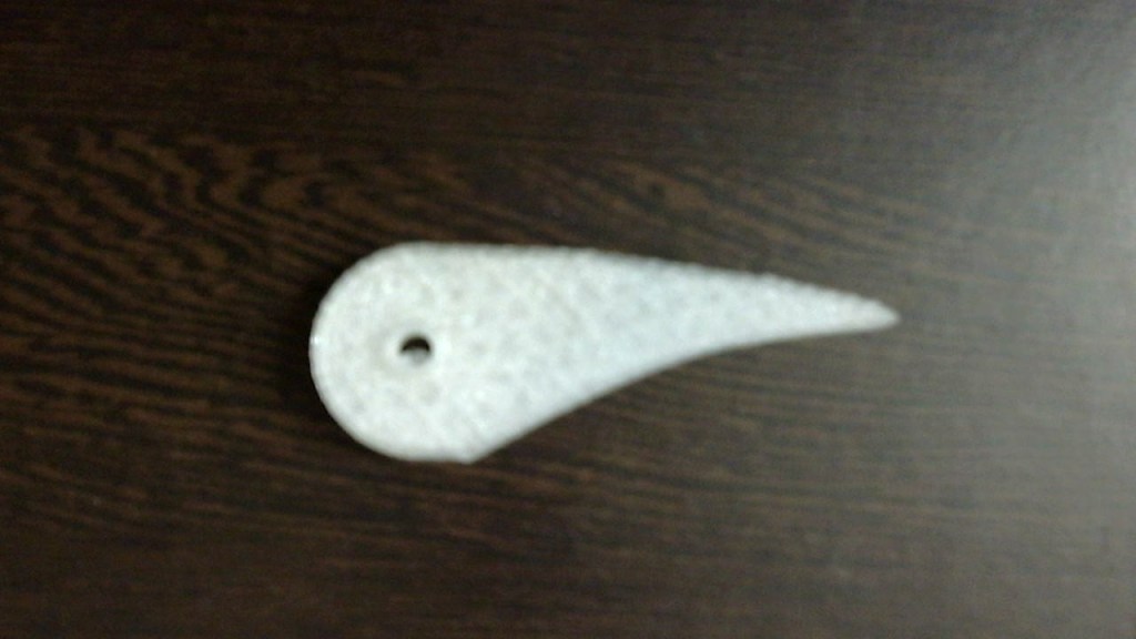
This the part that connects the to the patella which is known as the claw and there are 4 of these as well.
Electronics
On the electronics division, there are 4 main parts which are in the picture below.

Arduino mega
I could only use this board as there are many digital pins to operate servo’s. I maen, I could use a Giga R3, but it is not that cost effective and there are not much servo shields for this board.
HW-857 Servo Shield
I used this shield as it is perfect for servo connections which are more in number as well as a insulation from the arduino’s power and the servo,s power.
9V Battery
It is important to power the Arduino as there are a lot of servo motors which are going to be running and I am using 2 of these batteries.
Servo’s
I am using 20 Servo’s which have a arm force of about 1.6kg/cm each.
Assembling
I put all togather and found some problems and they are:-
1. Slipping
This is the biggest problem. All the joints are circle and looks like the circle was a little to big, I mean 1 hundredth of a millimeter. It looks easy to fix but when I tried to add some glue I don’t know, but is keeps on going into the servo and killing it completely. I killed like, 5 to 6 servos.
2. Femur
I had to make support on the up side as well because the entier legs wieght was stressed at the servos shaft and joint was giving away very easily in the preasure.
Fixing the problems.
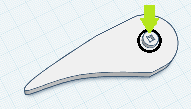
To fix the first problem, I had to re3Dprint all the parts with this tiny square shown in this Kad model pictures.
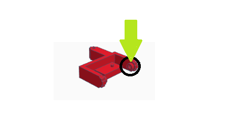
And the i fixed the second problem by making a new part like shown in the Kad picture.

This part fits on the back of the servo motor. Like shown in this Kad picture.
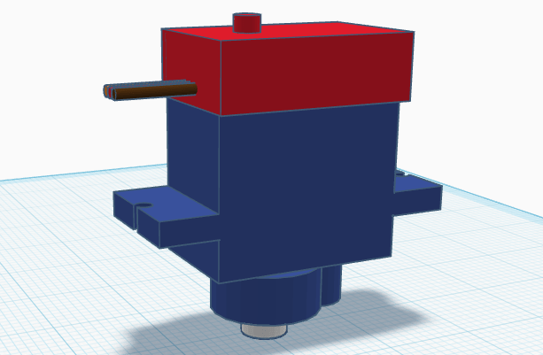
This gives like a dummy motor shaft on the other side which distributes the force equally among both the sides.
After fixing these problems I faced a huge problem.
When I tried to code it to move a couple of motors it did not have enough power to move and then I gave it about 9 volts, I forgot to remove the power jumper on the Arduino mega shield and then the Arduino processor started to burn out so i had to buy a new Arduino. and also, the motors were weak, so I decided to start the project from the beginning with a new Arduino, new motors and new parts.
Restart
I restarted by buying some high torque servo motors. I found this Tower Pro MG996r continuous rotation servo. which was way more powerful than the SG90 servo. As well as I was using 20 SG90 servo’s but because of this high torque servo I thought of using only 12. as buying 20 MG996r’s would make the bot bulky and is not that cost effective.
I also thought of using a PCA-9685, but it would interfere with the HC-05 Bluetooth module, as this bot is going to be controlled by Bluetooth.
Kad designing
I started off with designing the parts to fit the new big servo.
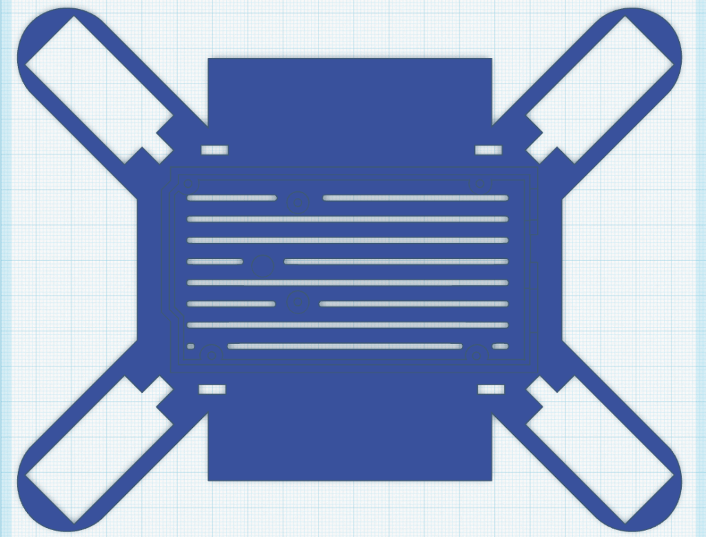
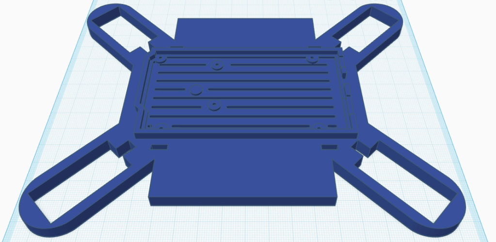
Today I finished designing the Chasi of the spider bot. This what it looks like.
This is the 2d top view of the Chasi.
And this is the 3d view of the Chasi.
I made some holes under the Arduino mega for future cooling as well as less print material being wasted.
And those rectangles on the sides are to place the batteries I could have placed them under, but the cooling fan which I might fix could not be installed.
The rectangular holes in every side close to the corner and either side of the Arduino housing is for the wire to come up to connect to the shield and not be messing around with the other servos and creating a mess.
Also, that little notch at every servo fitting to make sure that the wire of the servo goes in smoothly because it would bend and get smashed without it.

Leave a comment